Gridfinity Creator
About
GridfinityCreator lets you generate STL or STEP files for several types of customizable Gridfinity components. For each type you can specify size, but also other parameters and options such as compartments, magnet-and/or screw-holes, a stacking lip and more. Just fill in the parameters and click the "Generate" button.
Warning
GridfinityCreator is alpha software. It may produce incorrect output, fail inexplicably or cease to exist at any moment.
Alternatives
There are quite a few other Gridfinity generators available, both online and offline, each with their own advantages and use-cases. The ones I know about are:
- Online generator with a nice preview, by perplexinglabs
- Onlnie generator, based on an OpenSCAD implementation
- A Fusion360 Gridfinity App
- A python library to build Gridfinity objects
- Several Gridfinity generators by Printables user @jdegs
Made possible by ...
As is the case with most software these days, this application relies heavily on Free and Open Source Software (FOSS), generously released by their respective authors under an open license. Below is a list of the major tools, libraries and other components GridfinityCreator relies on:
- CadQuery (Python framework for procedural CAD modelling)
- Flask (Python web-application framework)
- Jinja2 (Python HTML template engine)
- Gunicorn (the WSGI server that runs GC)
- Python (the programming language GC was written in)
- Bootswatch/Flatly (the Bootstrap theme used for this site)
- VS Code (my IDE of choice)
- Git (for version control)
- Blender (used to the render the images of the components across the site)
- Docker (not FOSS, but still free as in beer)
Description
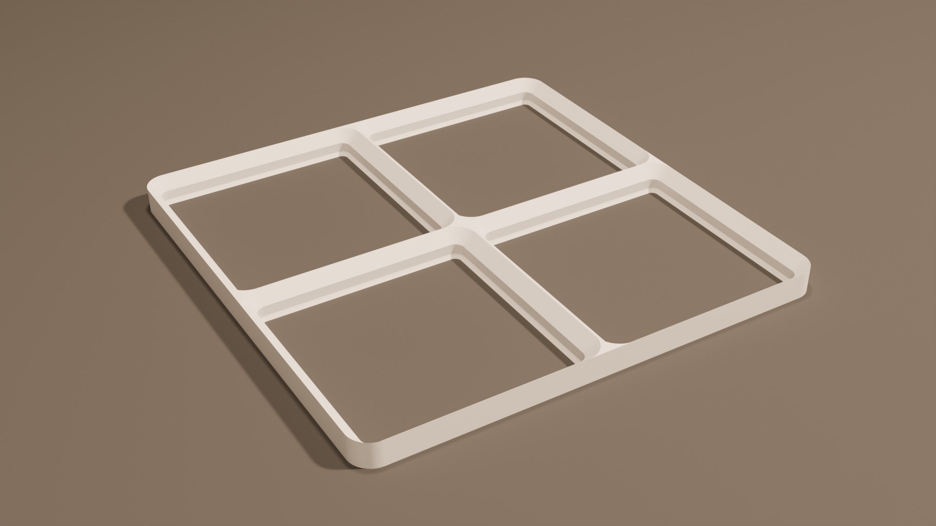
Bare bones baseplate. No screws or magnets, just the minimum required to snugly hold your bins.
Parameters
- Size: Width and Length of the baseplate in grid units (1 unit = 42mm)
- Other: Select the output format (STL or STEP)
Description
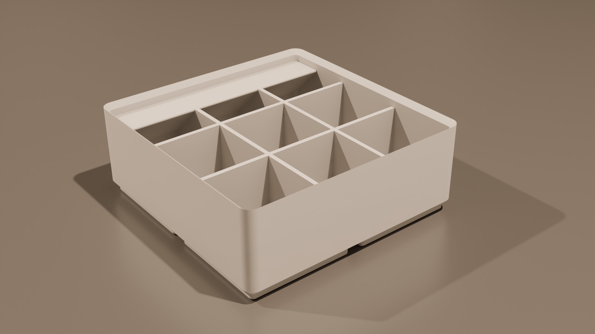
The basic divider bin. Create one of your desired size and with any number of compartments in both length and width directions.
Parameters
- Size: Width, Length and Height of the bin in grid units (42mm for Width and Length, 7mm for Height)
- Compartments: The number of compartments in the Length and Width direction
- Magnets: Control whether magnet holes should be added, their size, and if additional holes for screws and/or magnet removal should be added as well
- Labels: Control whether no label tab, a single label tab or a label tab for each row of compartments should be added
- Other: Select the output format (STL or STEP) and whether to include a stacking lip and/or scoop ramp
Description
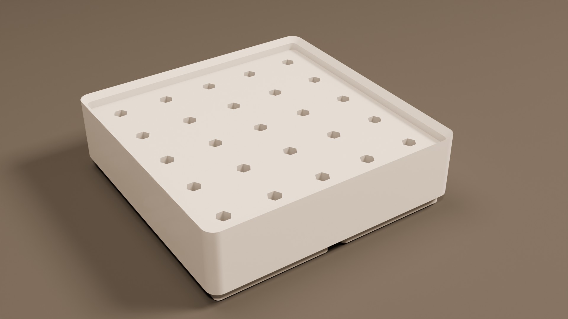
The holey bin is a solid Gridfinity bin with a configurable grid of holes (round, hex, square, etc). Useful for things like a screw-bit organizer or battery-storage. You cannot specify the size of the bin. Instead, the generator will determine the minimum bin-size that fits the specified hole-grid
Parameters
- Hole Grid: How many holes you want in the Width and Length directions. The generator will create a bin of the required size
- Holes: Control whether magnet holes should be added, their size, and if additional holes for screws and/or magnet removal should be added as well
- Other: Select the output format (STL or STEP) and whether to include a stacking lip
Description
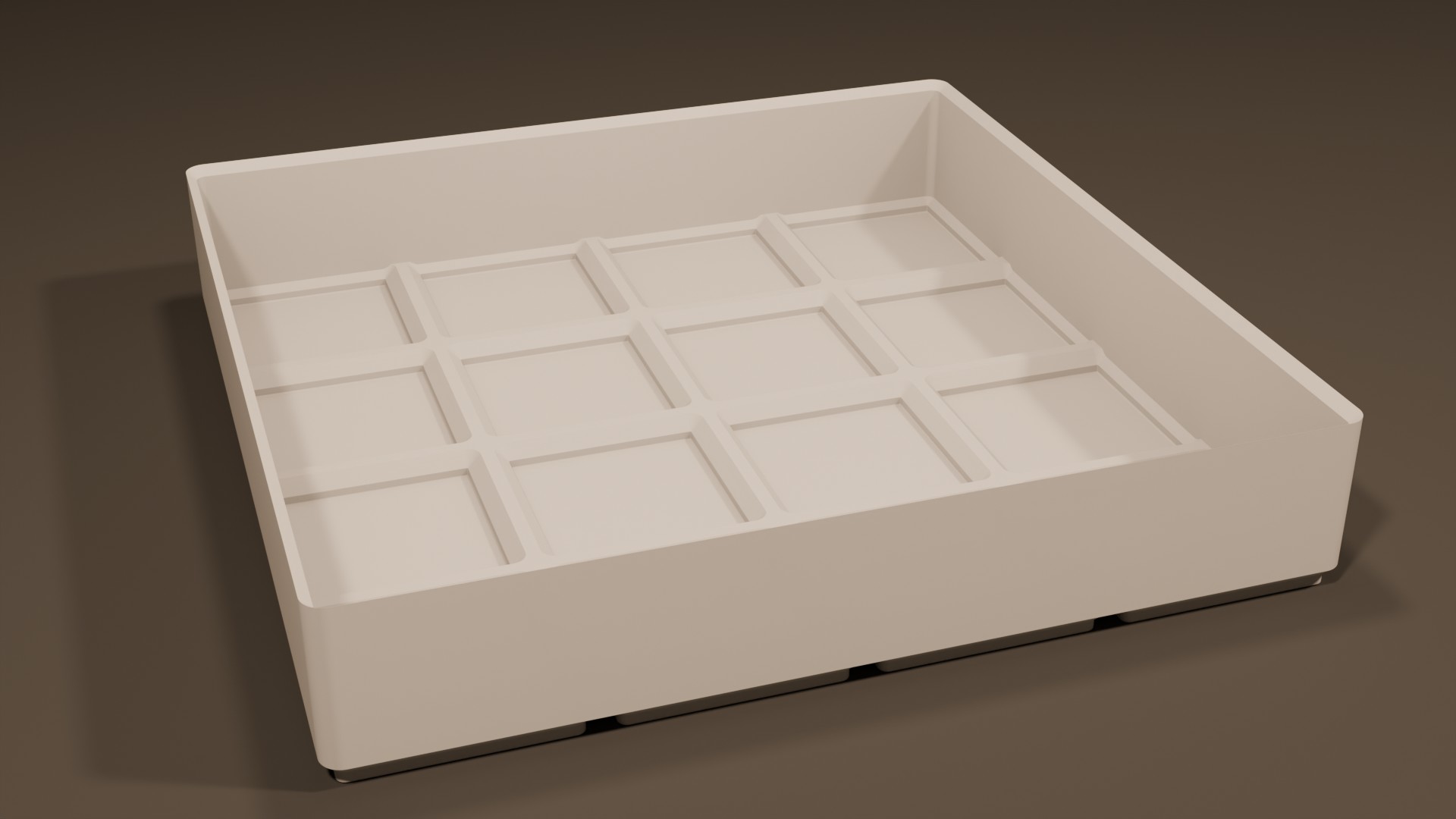
This generates a light version of the normal Gridfinity bin that saves plastic and offers more room. This means magnets and/or screws are not possible.
Parameters
- Size: Width, Length and Height of the bin in grid units (42mm for Width and Length, 7mm for Height)
- Other: Select the output format (STL or STEP) and whether to include a stacking lip
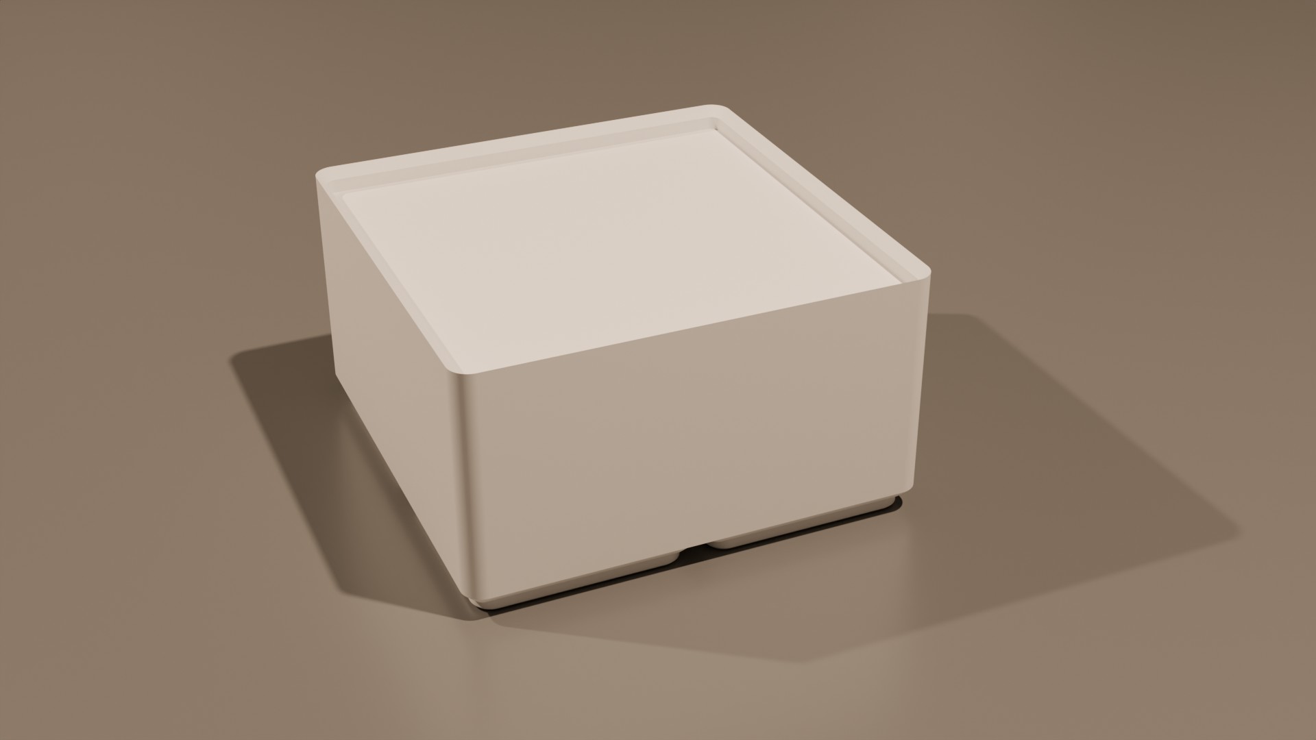
Description
The solid bin is a completely filled solid Gridfinity bin which can be used as a starting point for custom bins.
Parameters
- Size: Width, Length and Height of the bin in grid units (42mm for Width and Length, 7mm for Height)
- Magnets: Control whether magnet holes should be added, their size, and if additional holes for screws and/or magnet removal should be added as well
- Other: Select the output format (STL or STEP) and whether to include a stacking lip
Advanced settings
Below is the specification of the grid used by the generator to create components. You can select one of the presets or adjust the settings individually.
Note
All measurements are in millimeters
Beware
The defaults comply with the Gridfinity specification and have been tested to work well. Don't make any changes unless you have a good reason to do so and you know what you're doing.